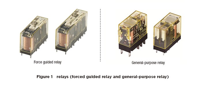
Figure 1 shows the appearance of a force guided relay and a general-purpose relay.
There are various types of relays, but the safety-related part of a machine’s control system (SRP/CS: Safety-Related Part of a Control System) uses force guided relays. In addition to its primary purpose of switching contacts, when it detects a welded contact failure of its own contacts, the force guided relay is also used for the purpose of maintaining a stop until a failure is resolved.
Structure and Operation of Force Guided Relays
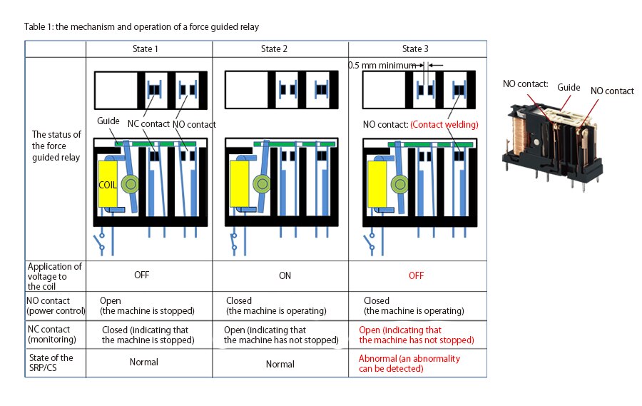
The structure and operation of a force guided relay are shown in Table 1.
In a force guided relay, the NO (normally open) and NC (normally closed) contacts are separated by a wall and are insulated from each other. The NO and NC contacts are mechanically connected by a link mechanism (guide), and operate in conjunction with each other depending on whether a voltage is supplied to the coil.
The main feature of the force guide relay is that this link mechanism (guide) keeps the NC contact open when the NO contact is welded together and remains closed as shown in state 3 in Table 1 below.
In Table 1, one NO contact and one NC contact are shown to illustrate the principle of the force guided relay, but in actual products, three NO contacts and one NC contact are generally used as one set.
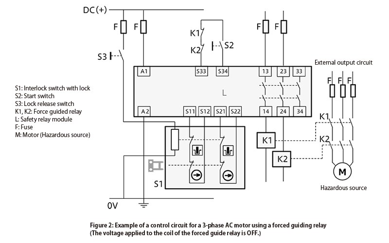
When actually using force guided relays, for example, K1 and K2 shown in Figure 2, for each of the two force guided relays, three NO contacts are connected to the power control circuit of 3-phase AC such as the machine motor, and one NC contact is connected to the monitoring circuit (between S33 and S34 in Figure 2).
By doing so, the machine is stopped when voltage applied to the coil is OFF as shown in state 1 in Table 1, and the machine is running only when the NO contact is closed while voltage applied to the coil is ON as shown in state 2 in Table 1. The use of NO contacts in the power control circuit also has a feature of making it easier to ensure safety because when the voltage applied to the coil is OFF due to wire disconnection or other causes, the NO contacts open, and the machine stops.
In this state, the NC contact is closed when the voltage applied to the coil is OFF (when the machine is stopped) as shown in state 1 in Table 1, and the NC contact is open when the voltage applied to the coil is ON as shown in state 2.
When a welded contact of the power control circuit occurs at the NO contact of K1 as shown in state 3 of Table 1, the NC contact of K1 in the monitoring circuit, which operates in conjunction with the guide, remains open even if the voltage to the coil is set to OFF. In this state, K2 is operating normally, and so the machine can be stopped by opening the three NO contacts of K2. By connecting the NC contacts of K1 and K2 in series to the monitoring circuit, the machine cannot be started even if the start switch of S2 is operated because the NC contacts remain open due to the effect of the welded NO contact of K1. Therefore, in order to restart the machine, the K1 force guided relay that is welded together must be replaced with a normal one.
Thus, by using two force guided relays, the machine can be stopped even if one of the NO contacts is welded together, and restarting can be prevented for maintaining the safety of the machine.
Other Failure Modes (Broken Plate Spring)
In terms of safety, breakage of plate springs is one of the most important failures that must be taken into account.
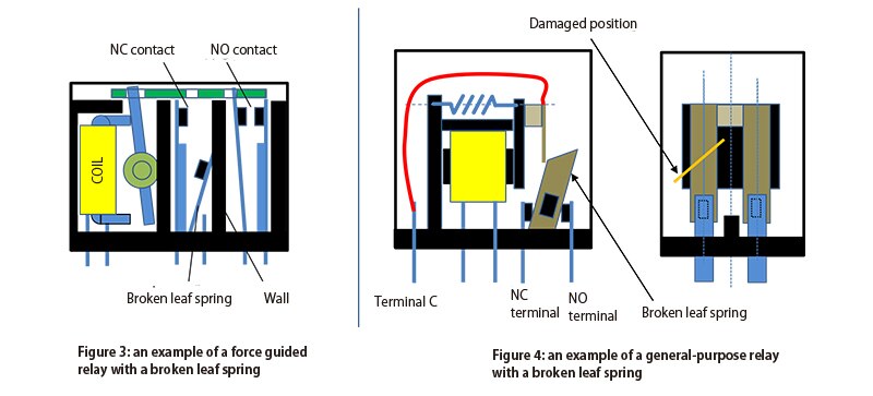
Figures 3 and 4 show the respective states of the force guided relay and general-purpose relay when the plate spring is broken.
In a force guided relay, the NO and NC contacts are separated by a wall .
Therefore, if the plate spring of one of the contacts breaks, it will not affect the other contact, and the impact is minimized.
On the other hand, general-purpose relays have a C-contact that integrates the NO and NC contacts. Therefore, a broken spring can cause both contacts to conduct and impact a neighboring system, which may cause the machine to start moving in an unintended motion or make it impossible to stop the machine when you try to stop it. For this reason, general-purpose relays cannot be used in the safety-related part of the control system.
Force Guided Relay Product Descriptions


